Medium-Voltage Ring Main Unit
Designed for applications with stringent compliance and safety requirements—such as utility grid acceptance projects, key municipal infrastructure developments, and public buildings—the solution is built upon a comprehensive mechanical interlocking system, multi-compartment segregation design, and full type-tested certification.
By effectively preventing operational errors and equipment failures through its structural design, the switchgear ensures a high level of operational safety and reliability while meeting the most demanding utility grid connection and acceptance standards. It is an ideal choice for projects requiring strict regulatory compliance, enhanced personnel protection, and long-term system dependability.
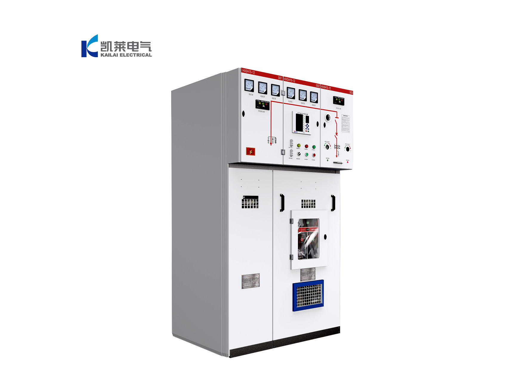
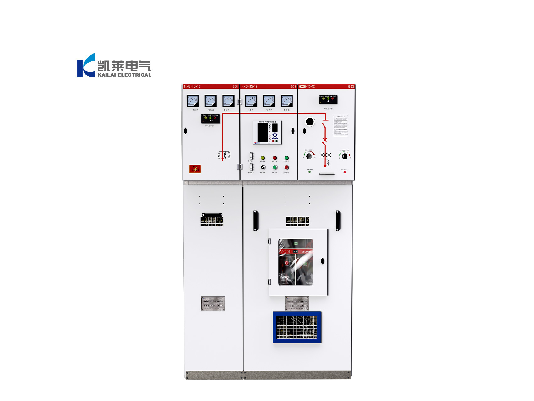
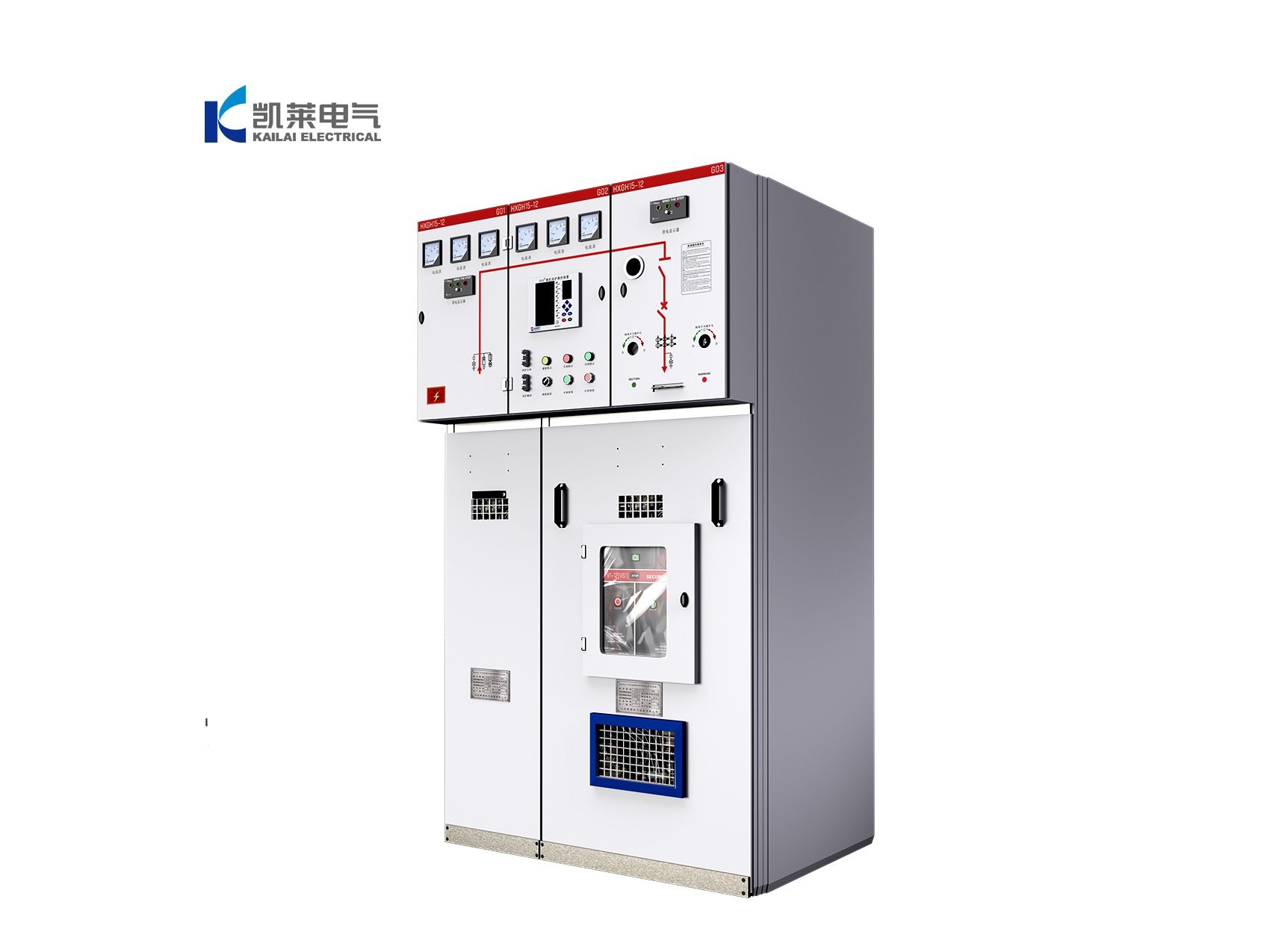
HXGN15-12 AC Metal-Enclosed Ring Main Unit
The HXGN15-12 is an AC high-voltage complete switchgear with a rated voltage of 12kV and a rated frequency of 50Hz. It is mainly used in three-phase AC ring networks, terminal distribution systems, and industrial electrical installations for power receiving, distribution, and protection. It is also suitable for installation in compact (prefabricated) substations.
This product complies with GB3906 “3–35kV AC Metal-Enclosed Switchgear”, GB/T11022 “Common Technical Requirements for High-Voltage Switchgear and Controlgear Standards”, IEC60298 “AC Metal-Enclosed Switchgear and Controlgear for Rated Voltages Above 1kV up to 52kV”, and IEC60694 “Common Specifications for High-Voltage Switchgear and Controlgear”. It is equipped with a complete “five-interlock” protection system.
Advantages & Features
1. Comprehensive Five-Prevention Mechanical Interlocking System
The switchgear integrates a three-way mechanical interlocking system between the load break switch, earthing switch, and cabinet door, fully implementing the “Five Prevention” safety functions:
Preventing incorrect opening or closing of the load break switch
Preventing operation of the isolating switch under load conditions
Preventing access to energized compartments
Preventing application of an earthing connection to energized circuits
Preventing circuit energization while the earthing switch is engaged
The entire system is protected by mandatory mechanical interlocks, eliminating the possibility of unsafe manual operation and fundamentally reducing risks to personnel and equipment.
2. Four Independent Compartment Segregation Design
The cabinet adopts a modular partitioned structure with separate busbar, switch, cable, and low-voltage control/instrument compartments. Each compartment is physically isolated to prevent fault propagation between circuits. This design effectively limits the spread of arc faults and short-circuit incidents while providing fully enclosed insulation protection for live parts, ensuring a high level of operational safety.
3. Comprehensive Type-Tested Certification
The complete switchgear assembly has successfully passed a full range of high-voltage type tests, including dielectric performance, temperature-rise verification, short-circuit withstand capability, dynamic and thermal stability tests, and mechanical endurance testing. In addition, every unit undergoes routine factory inspections, including dielectric withstand, insulation resistance, and circuit verification tests. Comprehensive documentation is provided to fully satisfy utility, municipal, and public project tendering and grid acceptance requirements.
4. Fast-Acting Fuse Protection System
Switch-fuse combination panels are equipped with current-limiting fuses that provide rapid protection against transformer and feeder short-circuit faults. In the event of a fault, the fuse operates instantly and triggers the automatic opening of the load break switch, isolating the faulted circuit within milliseconds. This highly effective protection mechanism minimizes the risk of equipment damage, cable failure, and electrical fire incidents.
Technical Parameters
| Item | Unit | Load Switch | Combination Unit |
Rated Voltage | kV | 12 | 12 |
Rated Frequency | Hz | 50 | 50 |
Power Frequency Withstand Voltage (phase-to-phase, phase-to-earth / across open contacts) | kV | 42 / 48 | 42 / 48 |
Lightning Impulse Withstand Voltage | kV | 75 / 85 | 75 / 85 |
Rated Current | A | 630 | 125 |
Rated Short-Circuit Making Current (peak) | kA | 50 | — |
Rated Peak Withstand Current | kA | 50 | — |
Rated Short-Time Withstand Current | kA / s | 20 / 4 | — |
Rated Short-Circuit Breaking Current | kA | — | 31.5 |
Rated Transfer Current | kA | — | 31.5 |
Max. Fuse Current | A | — | 125 |
Circuit Resistance | μΩ | ≤300 | ≤300 (excluding fuse) |
Auxiliary & Control Circuit Insulation Test | V | 2000 | 2000 |